Lecture 03
LED Control and Timing with the Raspberry Pi
Today, in one line
A GPIO pin is a voltage source that software can switch.
A very good switch. A mediocre clock.
When timing matters, move it out of the Python loop.
What changed since last week
Labs 1–2: the hardware decided.
From Lab 3: software decides. One line of Python changes a voltage.
The catch: Linux plus Python is a poor timekeeper. Measuring how poor is half the lab.
Where each task points
| Task | You do | Idea |
|---|---|---|
| 1–2 | boot, Python version, working directory | Linux guide |
| 3 | turn on one LED | numbering, resistor, set up / drive / clean up |
| 4 | blue and green alternate every 2 s; push the rate; jitter | loop period, scheduler jitter |
| 5 | three LEDs in sequence | several pins, per-colour current |
| 6 | RGB LED flashing three colours | common cathode vs common anode |
| 7 | PWM brightness; vary duty and frequency; scope | duty cycle, average voltage |
| 8 | RGB breathing | three PWM channels, gamma |
| 9 | copy work off, delete it | the Pis are shared |
The GPIO port
What a GPIO pin actually is
General-purpose: no fixed job. Input or output, your program decides.
As an output: push–pull. A 1 is 3.3 V, a 0 is 0 V.
A 3.3 V source with a switch, not a current source. Straight into an LED is the Lab 1 mistake, inside a computer.
Two numbering schemes for the same pins
BOARD
Physical position on the header, 1 to 40. Count with your finger.
BCM
The processor’s name, e.g. GPIO17. Gaps, not sequential. Used by datasheets and nearly all published code.
BCM, declared on the first line: GPIO.setmode(GPIO.BCM). Reports say “BCM 17 (physical 11)”.
The header
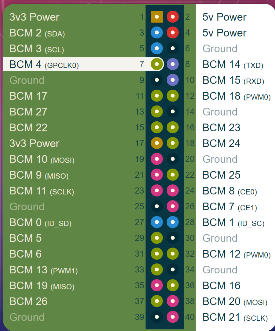
Pin 1 is the corner nearest the SD card.
Odd numbers down one row, even down the other.
Hardware PWM: BCM 12, 13, 18, 19.
Lab 3: 17, 27, 22 for LEDs; 18, 13, 19 for PWM.
The numbers that protect the Pi
| Limit | Value | Meaning for you |
|---|---|---|
| Output high | 3.3 V | every calculation uses 3.3 V |
| Maximum input | 3.3 V | not 5 V tolerant; 5 V kills the processor |
| One pin | 16 mA | design LEDs for 5–10 mA |
| All pins together | ∼50 mA | three LEDs at 8 mA fine; eight at 16 mA not |
| 5 V header pins | do not use | nothing in Lab 3 needs them |
There is no fuse between a pin and the processor.
Find pins at the bench, without Python
pinout                 # labelled diagram of this board
pinctrl get 17         # function and level of BCM 17
pinctrl set 17 op dh   # drive BCM 17 high
pinctrl set 17 op dl   # ...and low again
LED dark? Run pinctrl set 17 op dh first.
Lights: the bug is in software. Still dark: the bug is in the circuit.
Driving an LED
The circuit
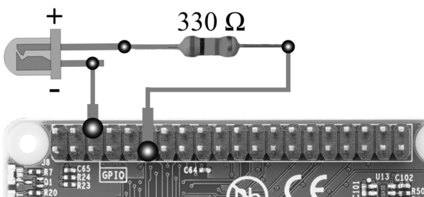
Pin → resistor → anode (long leg).
Cathode (short leg, flat rim) → ground.
470 Ω default; 330 Ω also fine.
Backwards: no harm, just dark.
Design from the current you want
Red, VF=2.0 V, 3.3 V pin: 470Ω→2.8mA, 330Ω→3.9mA.
Forward voltage depends on colour
| LED | VF | Headroom | I, 470 Ω | I, 330 Ω |
|---|---|---|---|---|
| Red | 1.8–2.0 V | 1.3–1.5 V | 2.8–3.2 mA | 3.9–4.5 mA |
| Yellow | 2.0–2.2 V | 1.1–1.3 V | 2.3–2.8 mA | 3.3–3.9 mA |
| Green | 2.0–2.4 V | 0.9–1.3 V | 1.9–2.8 mA | 2.7–3.9 mA |
| Blue | 2.7–3.0 V | 0.3–0.6 V | 0.6–1.3 mA | 0.9–1.8 mA |
Same resistor, a factor of three in current. Nothing is wrong.
Measure VF with the DMM diode test and tabulate it.
Talking to the pins
Every GPIO program has three parts
1. Set up: numbering scheme, which pins are outputs.
2. Drive: HIGH or LOW, usually in a loop with delays.
3. Clean up: release the pins when the program ends.
The RPi.GPIO vocabulary for Lab 3
| Call | What it does |
|---|---|
import RPi.GPIO as GPIO | the conventional import |
GPIO.setmode(GPIO.BCM) | interpret numbers as BCM names |
GPIO.setup(pin, GPIO.OUT) | a pin, or a list of pins, becomes an output |
GPIO.output(pin, GPIO.HIGH) | 3.3 V; GPIO.LOW is 0 V; lists work too |
GPIO.cleanup() | release every pin the script set up |
GPIO.PWM(pin, freq) | a PWM generator on an output pin |
sleep(seconds) | from time; a float; approximate |
The whole vocabulary. What you build from it is the assignment.
The one complete program: blink
import RPi.GPIO as GPIO
from time import sleep
GPIO.setmode(GPIO.BCM)             # 1. set up
GPIO.setup(17, GPIO.OUT)
try:
    for i in range(10):            # 2. drive
        GPIO.output(17, GPIO.HIGH); sleep(1.0)
        GPIO.output(17, GPIO.LOW);  sleep(0.5)
finally:
    GPIO.cleanup()                 # 3. clean up, even on Ctrl+C
range(1, 10) runs nine times, not ten.
Task 4: work it out on paper first
- How many pins? What does each
setupline look like? - Per loop pass: how many
outputcalls, in what order, so exactly one LED is lit? - Where do the
sleepcalls go? Predict the period before measuring it. - Put the delay in a named constant. Task 4d sweeps it.
Timing
sleep() is not a clock
Overhead only ever adds. The measured period is always longer.
Roughly constant in absolute terms, so it matters more as you go faster:
2 ms on 1.5 s is 0.1 %. 2 ms on 1 ms is 200 %.
What the scope shows
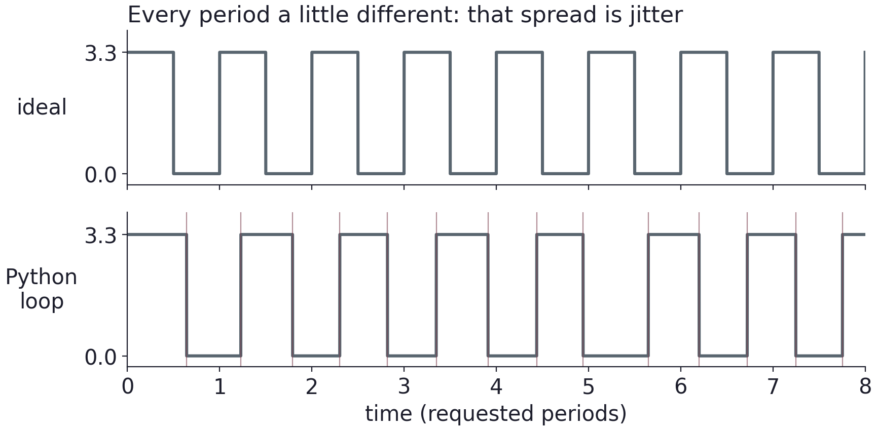
Where the extra time comes from
- Linux is not real-time: the scheduler can pause you at any moment
sleep()guarantees a minimum, not an exact delay- every
GPIO.output()is Python before it is hardware - garbage collection pauses, unpredictably
- the desktop, the network, the SD card all steal CPU
Name them in your report. “The Pi is slow” is not an explanation.
Measure jitter as a number
Scope: Period measurement, then Statistics on.
Infinite persistence, trigger on a rising edge: the most convincing screenshot.
Task 4 table: requested delay, expected f, measured f and T, jitter pk–pk and RMS, jitter as % of T.
Reading a statistics box
Loop written for 1 kHz. Over 500 cycles: Tmean=1.213 ms, Tmin=1.140, Tmax=1.760, σT=46μs.
Period error and frequency error differ. RMS small, pk–pk large: the scheduler’s signature.
Flicker fusion
Above roughly 50–90 Hz the LED stops flashing and looks dimmer.
The retina integrates over 10–20 ms and reports the average.
That is the bridge to PWM: switch faster than the eye, control the fraction.
Note where you stop seeing flicker; the scope still shows pulses.
PWM
Pulse-width modulation
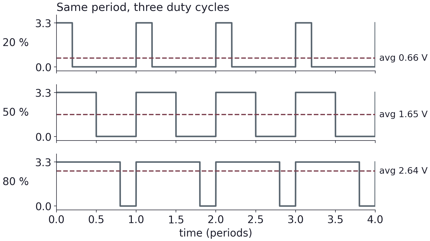
Frequency and duty are independent controls.
Software PWM calls
| Call | What it does |
|---|---|
pwm = GPIO.PWM(pin, freq) | PWM object on an output pin, freq in Hz |
pwm.start(duty) | begin; duty is a percentage, 0–100 |
pwm.ChangeDutyCycle(duty) | frequency untouched |
pwm.ChangeFrequency(freq) | duty untouched |
pwm.stop() | call before GPIO.cleanup() |
ChangeDutyCycle(0.5) is 0.5 %, which looks like off. Half brightness is 50.
Software PWM vs hardware PWM
GPIO.PWM() is always software: a thread toggles the pin, the scheduler can move every edge.
The Pi also has PWM peripherals on BCM 12, 13, 18, 19: a counter in silicon, no CPU per edge.
Task 7d: compare period statistics of your Task 4 loop and your PWM at the same frequency.
Predict before you look: 1 kHz, 30 %
T = ? ton = ? Vavg = ?
Now 500 Hz at 30 %: what changes, what does not?
A DMM on DC volts across the pin reads Vavg: a free cross-check.
RGB LEDs
One package, three dies, four legs
| Type | Common leg | Colour legs | Logic |
|---|---|---|---|
| Common cathode | ground | resistor, then a pin | HIGH = on. Prefer this. |
| Common anode | 3v3 | resistor, then a pin | LOW = on. All inverts. |
Longest leg is the common. The DMM diode test finds the type and each colour.
One resistor per colour. Shared, red hogs the current.
Breathing: why a linear ramp looks wrong
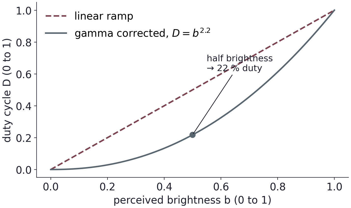
The eye is compressive.
Three PWM objects, a smooth b(t), one conversion line.
State the rule you used.
Scope settings for Tasks 4 and 7
| Probe | tip on the pin side of the resistor; ground clip on a header ground |
| Attenuation | 10×, and tell the scope |
| Coupling | DC. AC makes duty cycle meaningless |
| Trigger | edge, rising, ≈1.65 V |
| Measurements | Period, Frequency, +Width, Duty, then Statistics on |
| Display | infinite persistence for the jitter screenshot |
Name screenshots so you still understand them next week.
Destroys hardware / wastes your afternoon
5 V into a GPIO pin
LED with no resistor
power pin shorted to ground
rewiring with the Pi powered
a motor straight on a pin
BOARD/BCM mixed up
LED backwards
print() inside the timing loop
an old script still holding the pin
editing one file, running another
Before you leave: copy your work off, then delete it.
Take away
A GPIO pin is a software-controlled 3.3 V switch with a hard 16 mA limit: every load needs a resistor, every big load needs a transistor.
A Python loop places an edge to within milliseconds, and that error is constant, so it becomes fatal as you go faster.
To control an average, switch faster than the load can follow and vary the duty cycle.
Exit check
1. BCM name of physical pin 11?
2. Red LED, VF=1.9 V, 470 Ω, 3.3 V pin: current?
3. 0.5 ms high, 0.5 ms low requested; scope reads 1.31 ms. Overhead? Frequency error?
4. 200 Hz at 35 %: period, on-time, average voltage?
Use ← → to move, Home / End to jump, and F for fullscreen.
Figure descriptions
Slide 8 · The header
Raspberry Pi 40-pin header map distinguishing physical pin positions from BCM GPIO numbers and marking 3.3 V, 5 V, ground, I²C, UART, and SPI connections. Power pins are not GPIO inputs.
Slide 12 · The circuit
Raspberry Pi LED connection using a 330-ohm series resistor between a GPIO signal and the LED, with the return connected to ground. Verify physical pin numbers against the pinout before wiring.
Slide 22 · What the scope shows
Ideal evenly spaced digital pulses compared with pulses from a Python timing loop. The period varies slightly from cycle to cycle; this spread is timing jitter.
Slide 28 · Pulse-width modulation
Three 3.3 V PWM waveforms with equal period and duty cycles of 20, 50, and 80 percent. Their ideal average voltages are 0.66, 1.65, and 2.64 V.
Slide 34 · Breathing: why a linear ramp looks wrong
Linear and gamma-corrected LED brightness ramps. For the illustrated gamma of 2.2, a requested brightness of one half maps to approximately 22 percent duty cycle.