PHYS 351 · Lecture 05 01
Lecture 05
Stepper and Servo Motor Control Covers Lab 5
© Ran Yang, Ph.D. Advanced Instrumentation
PHYS 351 · Lecture 05 02
Today, in one line Until now: how fast, how bright. Never where .
Stepper : open loop. Command a sequence, count steps.
Servo : closed loop. Command a position, it corrects itself.
© Ran Yang, Ph.D. Advanced Instrumentation
PHYS 351 · Lecture 05 03
Where each task points Task You do Idea 1 NEMA 17 and driver datasheets; pins; four wires; schematic coils, windings, the driver 2 full-step and half-step tables, CW and CCW building a rotating field 3 two turns each way, both sequences; report runtime, revs, period, f f f step arithmetic 4 MG996R to 30 ∘ 30^\circ 3 0 ∘ pulse width to angle 5 full range; duty vs angle; fit; accuracy; reject bad input calibration, validation
© Ran Yang, Ph.D. Advanced Instrumentation
PHYS 351 · Lecture 05 04
The stepper
© Ran Yang, Ph.D. Advanced Instrumentation
PHYS 351 · Lecture 05 05
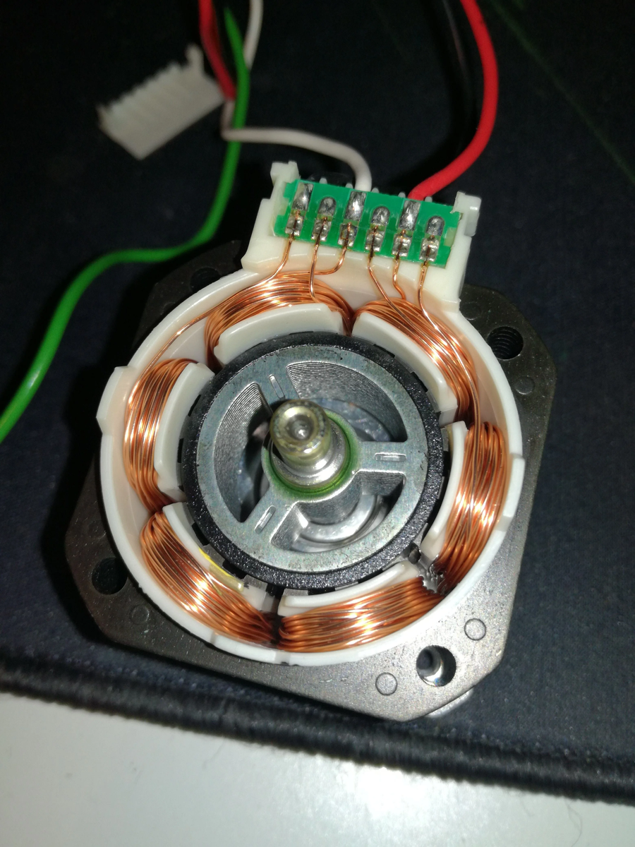
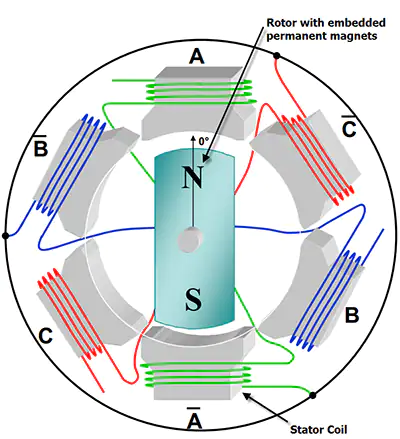
Inside a stepper Permanent-magnet rotor.
Two coil sets, A and B, on the stator.
Energise a combination: the rotor aligns and holds .
© Ran Yang, Ph.D. Advanced Instrumentation
PHYS 351 · Lecture 05 06
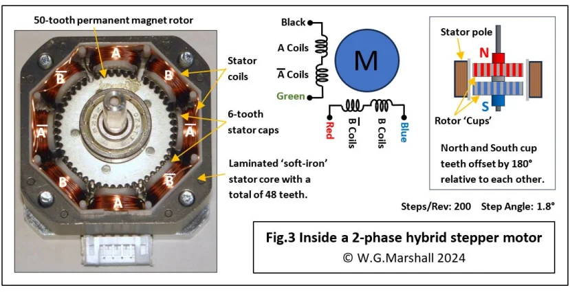
Why every step is the same size Alignments are fixed by the teeth.
Rotation is a sequence of jumps between them.
Count the jumps: you know the angle, with no sensor.
© Ran Yang, Ph.D. Advanced Instrumentation
PHYS 351 · Lecture 05 07
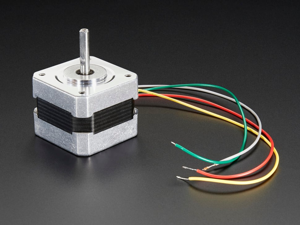
Four wires, two coils DMM on ohms, motor disconnected: same coil, a few ohms; different coils, open.
Short two leads and turn the shaft. Harder? That pair is one coil.
Wrong direction? Swap one pair.
© Ran Yang, Ph.D. Advanced Instrumentation
PHYS 351 · Lecture 05 09
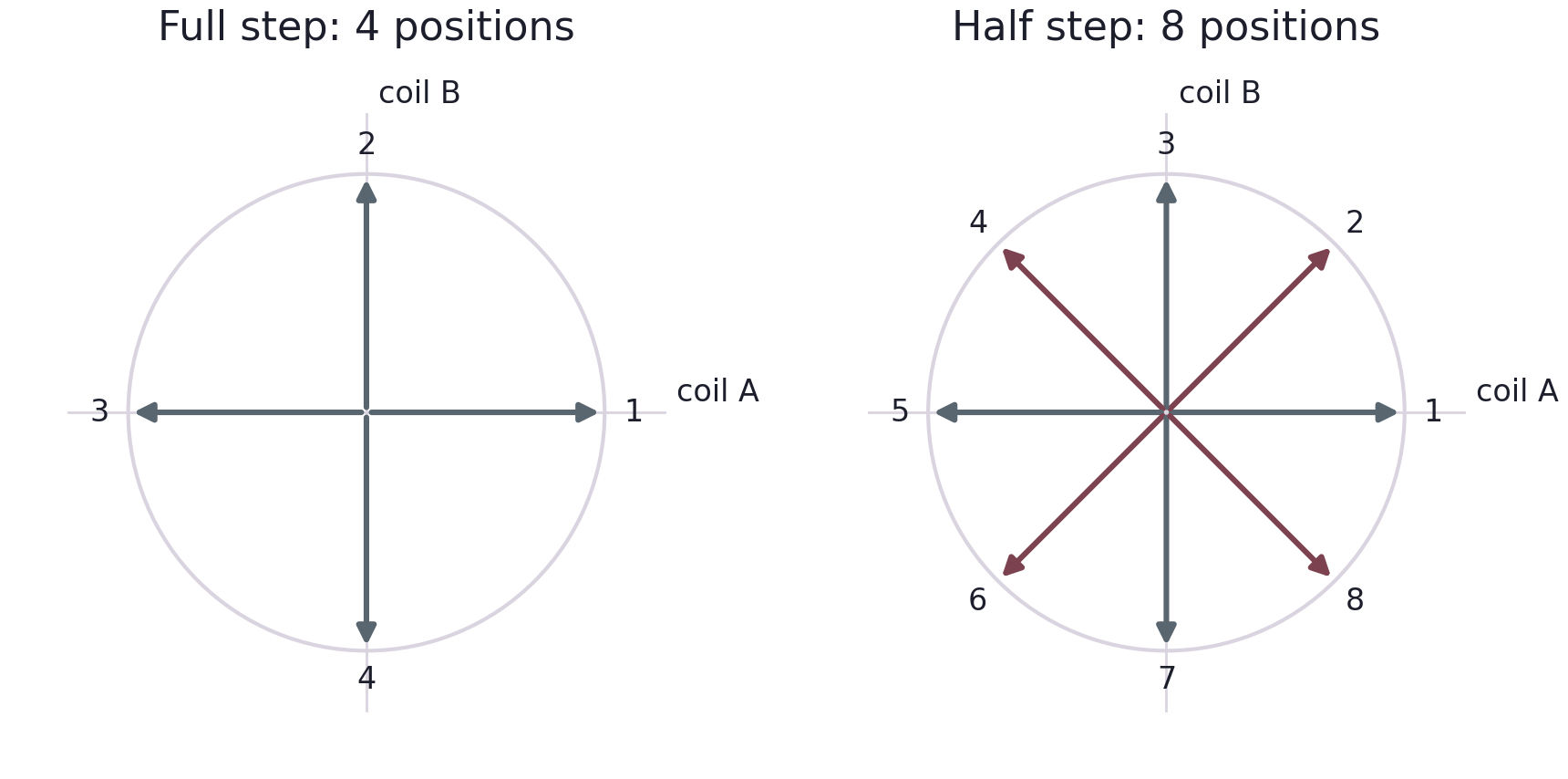
Task 2: the rule, not the table Write each state as the four driver inputs, in the datasheet’s notation.
Full step : one kind of state, four rows, repeat.
Half step : alternate axis and diagonal, eight rows.
Direction : walk the table the other way. One table, an index that counts up or down.
Sketch the field arrow for every row.
© Ran Yang, Ph.D. Advanced Instrumentation
PHYS 351 · Lecture 05 10
What each mode costs Mode Step angle Steps per rev Trade Full step θ full \theta_{\text{full}} θ full S S S more torque per step; coarser; more resonance Half step θ full / 2 \theta_{\text{full}}/2 θ full /2 2 S 2S 2 S twice the resolution; smoother; torque alternates; rate doubles
Task 3 wants both. Listen as well as watch.
© Ran Yang, Ph.D. Advanced Instrumentation
PHYS 351 · Lecture 05 11
The arithmetic θ step = 360 ∘ S n steps = rev × 360 ∘ θ step T rev = S t d RPM = 60 T rev \theta_{\text{step}} = \frac{360^\circ}{S}\qquad
n_{\text{steps}} = \text{rev}\times\frac{360^\circ}{\theta_{\text{step}}}\qquad
T_{\text{rev}} = S\,t_d\qquad \text{RPM} = \frac{60}{T_{\text{rev}}} θ step = S 36 0 ∘ n steps = rev × θ step 36 0 ∘ T rev = S t d RPM = T rev 60 1.8 ∘ 1.8^\circ 1. 8 ∘ t d = 5 t_d = 5 t d = 5 T rev T_{\text{rev}} T rev
© Ran Yang, Ph.D. Advanced Instrumentation
PHYS 351 · Lecture 05 12
Determine S S S Datasheet first, then verify : mark the shaft, command one revolution, does the mark return?
Two things silently change S S S gearbox , and a driver set to microstepping .
Wrong by a fixed factor, perfectly self-consistent. That is why Task 3 compares with observation.
© Ran Yang, Ph.D. Advanced Instrumentation
PHYS 351 · Lecture 05 13
Speed is limited by physics, not code Torque falls with rate : each coil is an inductor.
Missed steps : the rotor cannot reach the next alignment in time. The software has no idea.
Resonance : a narrow band of rates where torque collapses.
Motor misbehaves? Increase t d t_d t d
© Ran Yang, Ph.D. Advanced Instrumentation
PHYS 351 · Lecture 05 14
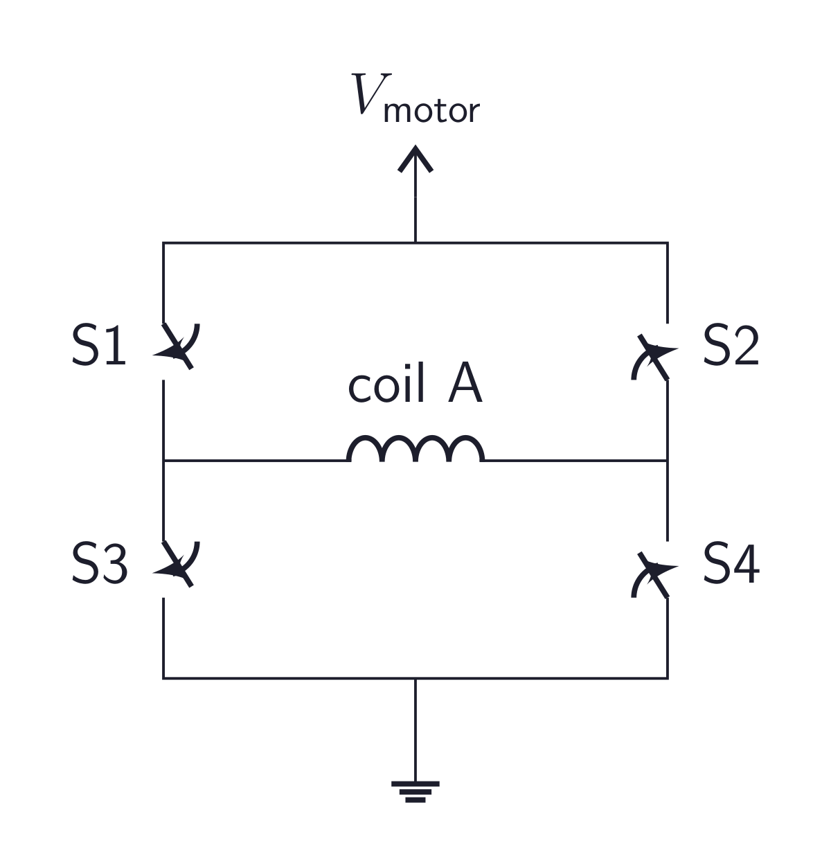
The driver: two H-bridges S1 and S4: current one way. S2 and S3: the other.
Four switches per coil, two coils, protection diodes, current limiting.
That is why you use a driver chip.
© Ran Yang, Ph.D. Advanced Instrumentation
PHYS 351 · Lecture 05 15
Task 1: what the schematic must show logic inputs from the Pi; coil outputs to the motor motor supply pin and voltage enable pin: active high or low? mode pins: full step or microstepping current limit, and how it is set Pi ground tied to motor-supply ground Never unplug a stepper with the driver powered
That is Lab 4’s inductive spike. It kills driver chips.
© Ran Yang, Ph.D. Advanced Instrumentation
PHYS 351 · Lecture 05 16
Reporting the numbers (Task 3c) Quantity Where it comes from Check it Total steps counted by your program against n steps n_{\text{steps}} n steps Angle per step datasheet ÷ \div ÷ mark, command, protractor Revolutions steps ÷ S \div S ÷ S count turns of the mark Runtime perf_counter() around the loopstopwatch Period, frequency S t d S\,t_d S t d 1 / t d 1/t_d 1/ t d scope on one driver input
S t d S\,t_d S t d
© Ran Yang, Ph.D. Advanced Instrumentation
PHYS 351 · Lecture 05 17
The servo
© Ran Yang, Ph.D. Advanced Instrumentation
PHYS 351 · Lecture 05 18
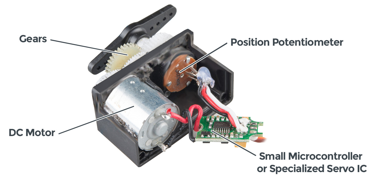
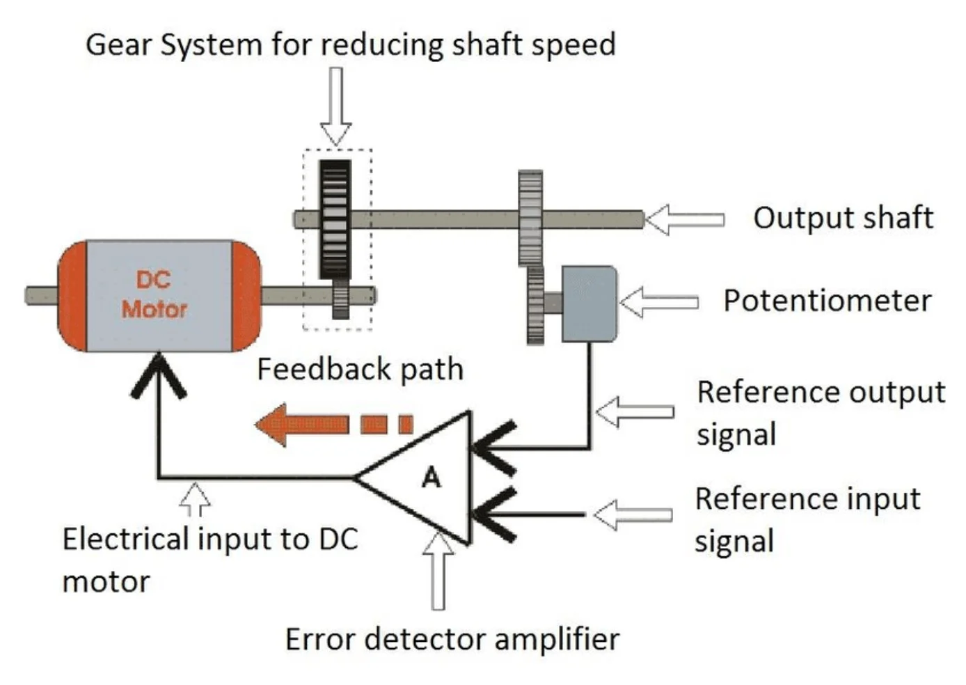
Inside a servo Motor, gearbox, a potentiometer on the output shaft, a controller. A feedback loop in a box.
© Ran Yang, Ph.D. Advanced Instrumentation
PHYS 351 · Lecture 05 19
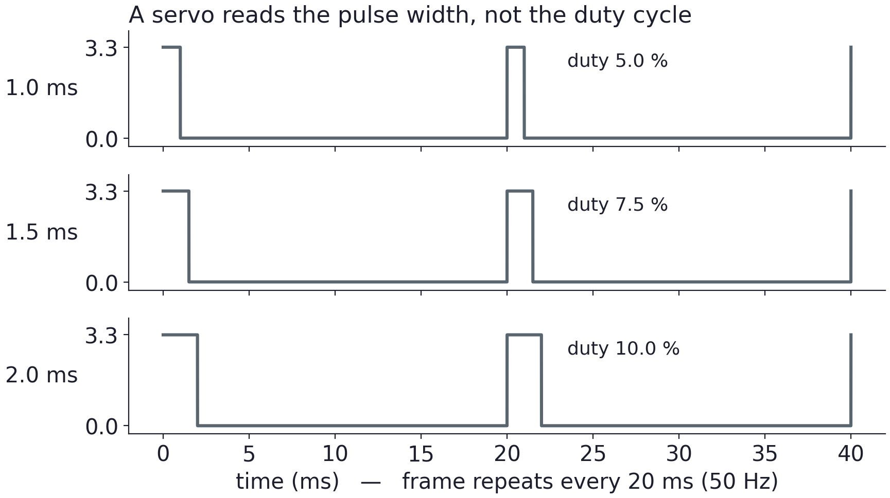
The command is a pulse width D = t pulse 20 ms × 100 D = \frac{t_{\text{pulse}}}{20\ \text{ms}}\times 100 D = 20 ms t pulse × 100 Only at 50 Hz.
Change the frequency and every duty number changes meaning.
© Ran Yang, Ph.D. Advanced Instrumentation
PHYS 351 · Lecture 05 20
Try it At 50 Hz: 5 % → \rightarrow → → \rightarrow → → \rightarrow →
The same duty at 100 Hz: what pulse does the servo see?
The reference code sweeps wider than 5–10 % for the MG996R’s full travel. Verify on the scope.
© Ran Yang, Ph.D. Advanced Instrumentation
PHYS 351 · Lecture 05 21
Approach the limits carefully A stalled servo strips its own gears
Past the mechanical range it drives into the end stop and buzzes. Step towards each end in small increments. Buzz means back off.
Record the last duty that gave clean motion. That is your usable limit.
Never force the horn by hand. Remove it and reinstall it.
© Ran Yang, Ph.D. Advanced Instrumentation
PHYS 351 · Lecture 05 22
Taking calibration data (Task 5) servo fixed; protractor centred on the horn pivot small, even duty steps; let it settle before reading record commanded duty, measured pulse width , measured angle sweep both directions: the difference is backlash The measured pulse width separates a software error from a servo property.
© Ran Yang, Ph.D. Advanced Instrumentation
PHYS 351 · Lecture 05 23
Judge the fit honestly A straight line, angle against duty. Slope and intercept, with units.
plot the residuals : curvature is the servo, scatter is repeatability compare the measured range with the datasheet smallest angle you can command and see a degree or two of scatter is the device floor. Say so. © Ran Yang, Ph.D. Advanced Instrumentation
PHYS 351 · Lecture 05 24
Validate the input (Task 5, last part) Out of range → \rightarrow →
Not a number → \rightarrow →
Valid → \rightarrow →
Enforce the range you measured, not 0–180∘ ^\circ ∘
© Ran Yang, Ph.D. Advanced Instrumentation
PHYS 351 · Lecture 05 25
Destroys hardware Do not
unplug a stepper with the driver powered
Secure both motors. Hands clear while energised.
© Ran Yang, Ph.D. Advanced Instrumentation
PHYS 351 · Lecture 05 26
Take away A stepper gives position by construction: energise in order and count. It fails silently when pushed past its torque.
A servo gives position by feedback: send a pulse width and it corrects, but only inside a range you measured.
Both need their own supply, a shared ground, and a calibration you performed.
© Ran Yang, Ph.D. Advanced Instrumentation
PHYS 351 · Lecture 05 27
Exit check 1. 1.8 ∘ 1.8^\circ 1. 8 ∘
2. 4 ms delay, full step: step frequency, revolution period, RPM?
3. 50 Hz: which duty gives 1.5 ms? Same duty at 100 Hz?
4. Which two leads are one coil, and how do you know?
© Ran Yang, Ph.D. Advanced Instrumentation
Use ← → to move, Home / End to jump, and F for fullscreen.
Figure descriptions Slide 5 · Inside a stepper Opened stepper motor exposing the rotor and surrounding copper stator windings connected to colored leads.
Stepper-motor concept: a permanent-magnet rotor is surrounded by stator coils A, B, and C. Sequential coil excitation rotates the magnetic field and moves the rotor.
Slide 6 · Why every step is the same size Hybrid stepper cutaway: toothed stator poles surround a 50-tooth permanent-magnet rotor. Offset north and south rotor cups enable 200 steps per revolution, or 1.8 degrees per step. © W. G. Marshall 2024.
Slide 7 · Four wires, two coils NEMA 17 stepper motor with a square body, output shaft, mounting holes, and four coil leads. Photo: Adafruit.
Slide 8 · Building a rotating field Magnetic-field vectors for stepping: a four-position sequence uses the coil axes; an eight-position half-step sequence adds intermediate diagonal directions by energizing both coils.
Slide 14 · The driver: two H-bridges H-bridge for motor coil A: switches S1 and S2 connect the coil ends to the motor supply; S3 and S4 connect them to ground. Opposite diagonal switch pairs reverse coil current. Closing both switches on one supply leg would short the supply.
DRV8833 dual motor-driver breakout board with labeled motor outputs, input pins, sleep and fault pins, power connections, terminal block, and header pins. Photo: Adafruit.
Slide 18 · Inside a servo Opened hobby servo showing a DC motor, reduction gears, position potentiometer, and a small control circuit.
Servo feedback loop: a reference input is compared with position feedback from a potentiometer; the error amplifier drives a DC motor through reduction gears to the output shaft.
Slide 19 · The command is a pulse width Servo control pulses repeat every 20 ms. Illustrated high times of 1.0, 1.5, and 2.0 ms encode different positions; pulse width, rather than duty cycle alone, is the command.
Complete notes Lab 5 manual