PHYS 351 · Lecture 06 01
Lecture 06
Serial Protocols, I2 C and the MCP9808 Covers Lab 6
© Ran Yang, Ph.D. Advanced Instrumentation
PHYS 351 · Lecture 06 02
Today, in one line A digital sensor does not send you a temperature.
It sends bits from a numbered register , in a format the datasheet defines.
The protocol delivers the bits. The datasheet gives them meaning.
© Ran Yang, Ph.D. Advanced Instrumentation
PHYS 351 · Lecture 06 03
Where each task points Task You do Idea 1 lab directory; enable I2 C in raspi-config; reboot bringing the bus up 2 wire with the Pi off; i2cdetect -y 1 shows 18; provided module; note its limit bus, address, resolution 3 write read_temp_high_res() for exactly 0.125 ∘ C 0.125\degC 0.12 5 ∘ C register layout, decoding 4 ∘ ^\circ ∘ ∘ ^\circ ∘ reading to dataset 5 optional live scrolling plot
V D D V_{DD} V D D
© Ran Yang, Ph.D. Advanced Instrumentation
PHYS 351 · Lecture 06 04
Serial communication
© Ran Yang, Ph.D. Advanced Instrumentation
PHYS 351 · Lecture 06 05
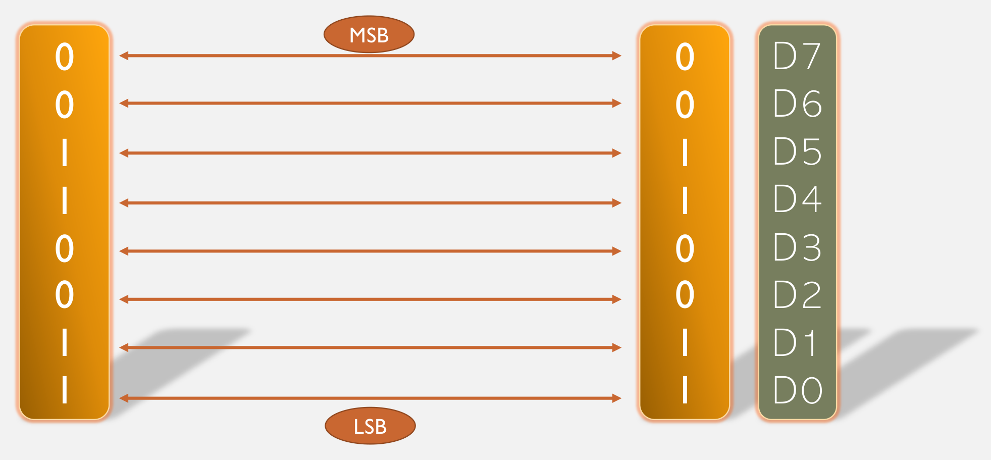
Two ways to move a byte Parallel: eight wires, one tick
Serial: one wire, eight ticks, MSB first
Which is faster?
© Ran Yang, Ph.D. Advanced Instrumentation
PHYS 351 · Lecture 06 06
Serial won Interface Year Type MB per second PATA, Parallel ATA 1986 parallel 66 / 100 / 133 SATA, Serial ATA 2003 serial 150 / 300 / 600
Skew : eight bits must arrive together; the worst wire sets the clock.
Crosstalk : eight lines switching together couple into each other.
Pins : the scarcest resource on a 40-pin header.
© Ran Yang, Ph.D. Advanced Instrumentation
PHYS 351 · Lecture 06 07
Asynchronous or synchronous Family How timing is agreed Examples Asynchronous no clock sent; both ends preset to one baud rate UART, USB. Wrong baud = garbage Synchronous a clock line travels with the data I2 C (Lab 6), SPI (Lab 8)
One extra wire buys freedom from a baud-rate agreement.
© Ran Yang, Ph.D. Advanced Instrumentation
PHYS 351 · Lecture 06 08
The I2 C bus
© Ran Yang, Ph.D. Advanced Instrumentation
PHYS 351 · Lecture 06 09
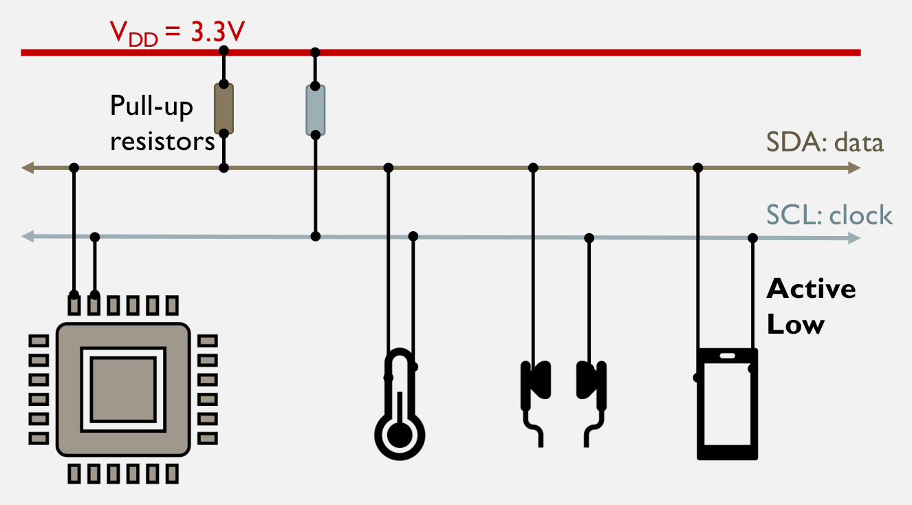
Two wires, any number of devices SDA carries data, SCL the clock. The Pi starts every transaction.
© Ran Yang, Ph.D. Advanced Instrumentation
PHYS 351 · Lecture 06 10
Open drain, pull-ups, active low Every device can only pull a line down . Pull-up resistors pull it up.
Two devices can never fight: the worst case is both pulling low.
Idle is both lines high. Low wins. No pull-ups, no bus.
The Adafruit breakout and the Pi both carry pull-ups. You add none.
© Ran Yang, Ph.D. Advanced Instrumentation
PHYS 351 · Lecture 06 13
The rule that makes both unmistakable During data
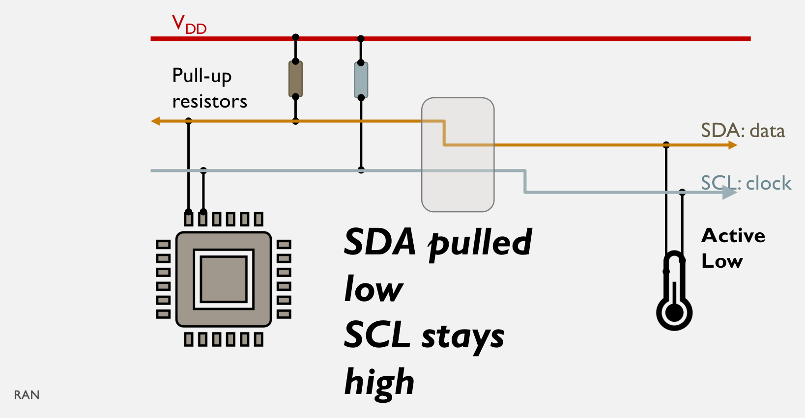
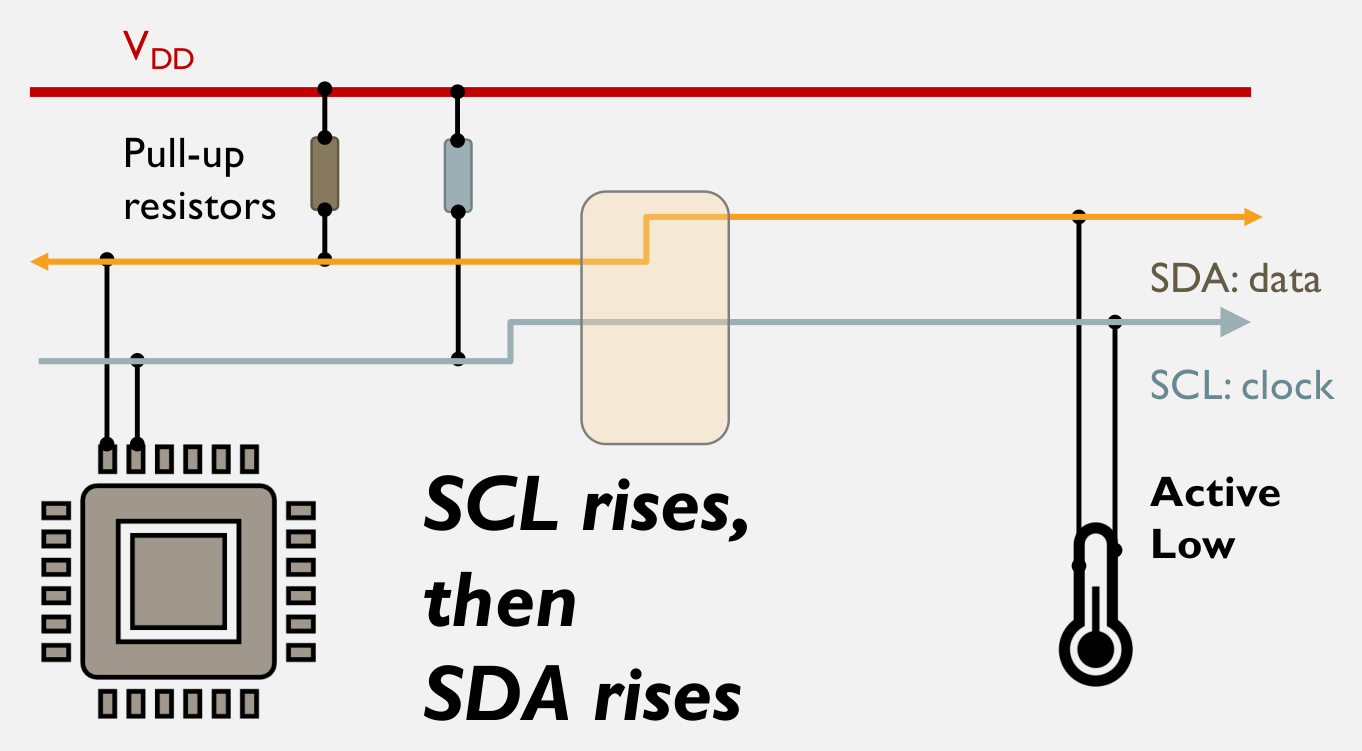
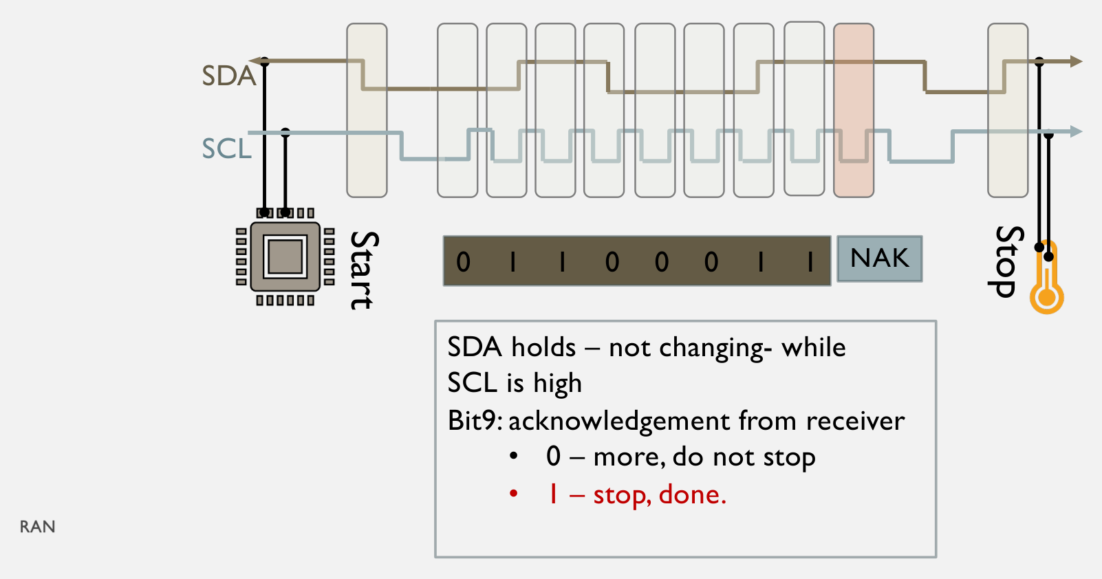
SDA holds steady while SCL is high. SDA changes only while SCL is low. The receiver samples on the rising edge.
So an SDA transition while SCL is high cannot be data.
It can only be START or STOP. One rule gives sampling and framing.
© Ran Yang, Ph.D. Advanced Instrumentation
PHYS 351 · Lecture 06 16
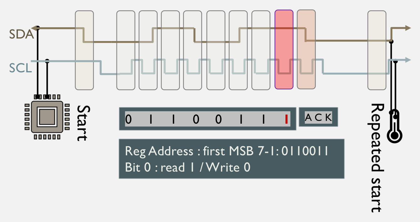
Address byte: 7 bits plus a direction
Bit 0 = 1 read, 0 write. MCP9808: 7-bit 0x18; shifted, 0x30 write, 0x31 read.
Linux and Python use the 7-bit form.
© Ran Yang, Ph.D. Advanced Instrumentation
PHYS 351 · Lecture 06 17
A complete register read START device address + write → \rightarrow → register pointer → \rightarrow → repeated START device address + read → \rightarrow → first byte in; controller sends ACK: “another” second byte in; controller sends NAK: “enough” STOP © Ran Yang, Ph.D. Advanced Instrumentation
PHYS 351 · Lecture 06 18
The MCP9808
© Ran Yang, Ph.D. Advanced Instrumentation
PHYS 351 · Lecture 06 19
Four blocks, four wires sensor ⋅ \cdot ⋅ ⋅ \cdot ⋅ ⋅ \cdot ⋅ 2 C
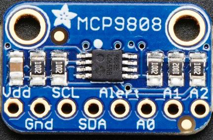
Sensor Pi VDD 3.3 V, physical 1 or 17 not 5 V GND any ground SDA BCM 2, physical 3 SCL BCM 3, physical 5
Alert, A0–A2: leave unconnected.
Wire with the Pi off . VDD/GND swapped kills the sensor.
© Ran Yang, Ph.D. Advanced Instrumentation
PHYS 351 · Lecture 06 20
The register map Register Pointer Access Contents / power-up Configuration 0x01 R/W 0x0000 T upper / lower / critical 0x02 / 0x03 / 0x04 R/W 0x0000 Ambient temperature T A T_A T A 0x05 R the measurement Manufacturer ID 0x06 R 0x0054 , fixedDevice ID / revision 0x07 R 0x0400 , fixedResolution 0x08 R/W 0x03 at power-up
Best debugging trick in this lab
Read 0x06 first. 0x0054 back proves wiring, address and library at once.
© Ran Yang, Ph.D. Advanced Instrumentation
PHYS 351 · Lecture 06 21
The ambient temperature register, bit by bit bit 15 14 13 12 11 10 9 8 means T A ≥ T crit T_A\!\ge\!T_{\text{crit}} T A ≥ T crit T A > T up T_A\!>\!T_{\text{up}} T A > T up T A < T low T_A\!<\!T_{\text{low}} T A < T low sign 2 7 2^7 2 7 2 6 2^6 2 6 2 5 2^5 2 5 2 4 2^4 2 4 bit 7 6 5 4 3 2 1 0 means 2 3 2^3 2 3 2 2 2^2 2 2 2 1 2^1 2 1 2 0 2^0 2 0 0.5 0.5 0.5 0.25 0.25 0.25 0.125 0.125 0.125 0.0625 0.0625 0.0625
Three flags, a sign, eight integer bits, four fraction bits.
Which fraction bits must you keep for exactly 0.125 ∘ C 0.125\degC 0.12 5 ∘ C
© Ran Yang, Ph.D. Advanced Instrumentation
PHYS 351 · Lecture 06 22
Decode + 17.75 ∘ C +17.75\degC + 17.7 5 ∘ C 1100 0001 0001 1100
Strip the flags ⋅ \cdot ⋅ ⋅ \cdot ⋅ ⋅ \cdot ⋅ 16 + 1 16+1 16 + 1 ⋅ \cdot ⋅ 0.5 + 0.25 0.5+0.25 0.5 + 0.25
© Ran Yang, Ph.D. Advanced Instrumentation
PHYS 351 · Lecture 06 23
Decode − 17.75 ∘ C -17.75\degC − 17.7 5 ∘ C 0011 1110 1111 1100 bit 12 set: below zero, two’s complement.
Assemble 224 + 15 = 239 224 + 15 = 239 224 + 15 = 239 ⋅ \cdot ⋅ 256 − 239 = 17 256 - 239 = 17 256 − 239 = 17 ⋅ \cdot ⋅ ⋅ \cdot ⋅
© Ran Yang, Ph.D. Advanced Instrumentation
PHYS 351 · Lecture 06 24
Resolution register 0x08: finer costs time Bits 1–0 Resolution Conversion 00 0.5 ∘ C 0.5\degC 0. 5 ∘ C 30 ms fastest 01 0.25 ∘ C 0.25\degC 0.2 5 ∘ C 65 ms 10 0.125 ∘ C 0.125\degC 0.12 5 ∘ C 130 ms 11 0.0625 ∘ C 0.0625\degC 0.062 5 ∘ C 250 ms power-up default (0x03)
Two “resolutions”: what the hardware measures, and how many fraction bits your code keeps. Task 3 is the second.
Poll faster than the conversion and you re-read the same value.
© Ran Yang, Ph.D. Advanced Instrumentation
PHYS 351 · Lecture 06 25
Bringing the bus up (no internet needed) sudo raspi-config # Interface Options -> I2C; reboot
ls /dev/i2c-* # the bus device exists?
i2cdetect -y 1 # the MCP9808 appears as 18
i2cget -y 1 0x18 0x06 w # manufacturer IDEmpty grid: VDD and GND first, then SDA/SCL, then swapped.
Run i2cdetect before one line of Python.
© Ran Yang, Ph.D. Advanced Instrumentation
PHYS 351 · Lecture 06 26
From a reading to a dataset (Task 4) T ∘ F = 9 5 T ∘ C + 32 T_{^\circ\mathrm{F}} = \tfrac{9}{5}\,T_{\degC} + 32 T ∘ F = 5 9 T ∘ C + 32 threshold in a named constant; demonstrate it with a finger perf_counter() for elapsed time; collect in a list, plot afterwardsCSV headers exactly as specified; open it and look warm the sensor mid-run: rise, peak, decay © Ran Yang, Ph.D. Advanced Instrumentation
PHYS 351 · Lecture 06 27
A debugging order that works 1. /dev/i2c-1 exists? No: enable, reboot.
2. i2cdetect shows 18? No: wiring or power, not code.
3. Register 0x06 reads 0x0054? No: byte order or library use.
4. Print the two raw bytes in hex. Decode by hand.
5. Both signs handled? Feed it the known byte pairs.
© Ran Yang, Ph.D. Advanced Instrumentation
PHYS 351 · Lecture 06 28
Destroys hardware / wastes your afternoon Destroys hardware
VDD and GND swapped
Wastes your afternoon
SDA and SCL swapped
© Ran Yang, Ph.D. Advanced Instrumentation
PHYS 351 · Lecture 06 29
Take away Two wires shared by every device, pull-ups making the bus active low so nobody can fight for it.
A transaction: START, address plus direction, register pointer, data, an acknowledge on every byte, STOP.
What comes back is sixteen bits whose meaning the datasheet defines. Reading them correctly, and proving it on known values, is Task 3.
© Ran Yang, Ph.D. Advanced Instrumentation
PHYS 351 · Lecture 06 30
Exit check 1. Address 0x18: the full first byte for a read, and for a write?
2. Why does a missing device produce NAK without doing anything?
3. Decode upper 0x01, lower 0x91.
4. Which two registers hold constants? Why read first?
© Ran Yang, Ph.D. Advanced Instrumentation
Use ← → to move, Home / End to jump, and F for fullscreen.
Figure descriptions Slide 5 · Two ways to move a byte Eight-bit parallel transfer: bits D7 through D0 travel simultaneously on eight separate signal lines between devices.
Eight-bit serial transfer: bits of a byte travel one after another on a single signal line, beginning with the most-significant bit in this illustration.
Slide 9 · Two wires, any number of devices Shared I²C bus: a controller and multiple devices connect to SDA and SCL. Both lines are pulled up to 3.3 V; devices signal low by pulling a line toward ground.
Slide 11 · START: SDA falls while SCL is high I²C start condition: SDA falls from high to low while SCL remains high.
Slide 12 · STOP: SCL rises, then SDA rises I²C stop condition: SCL is high when SDA rises from low to high, releasing the bus.
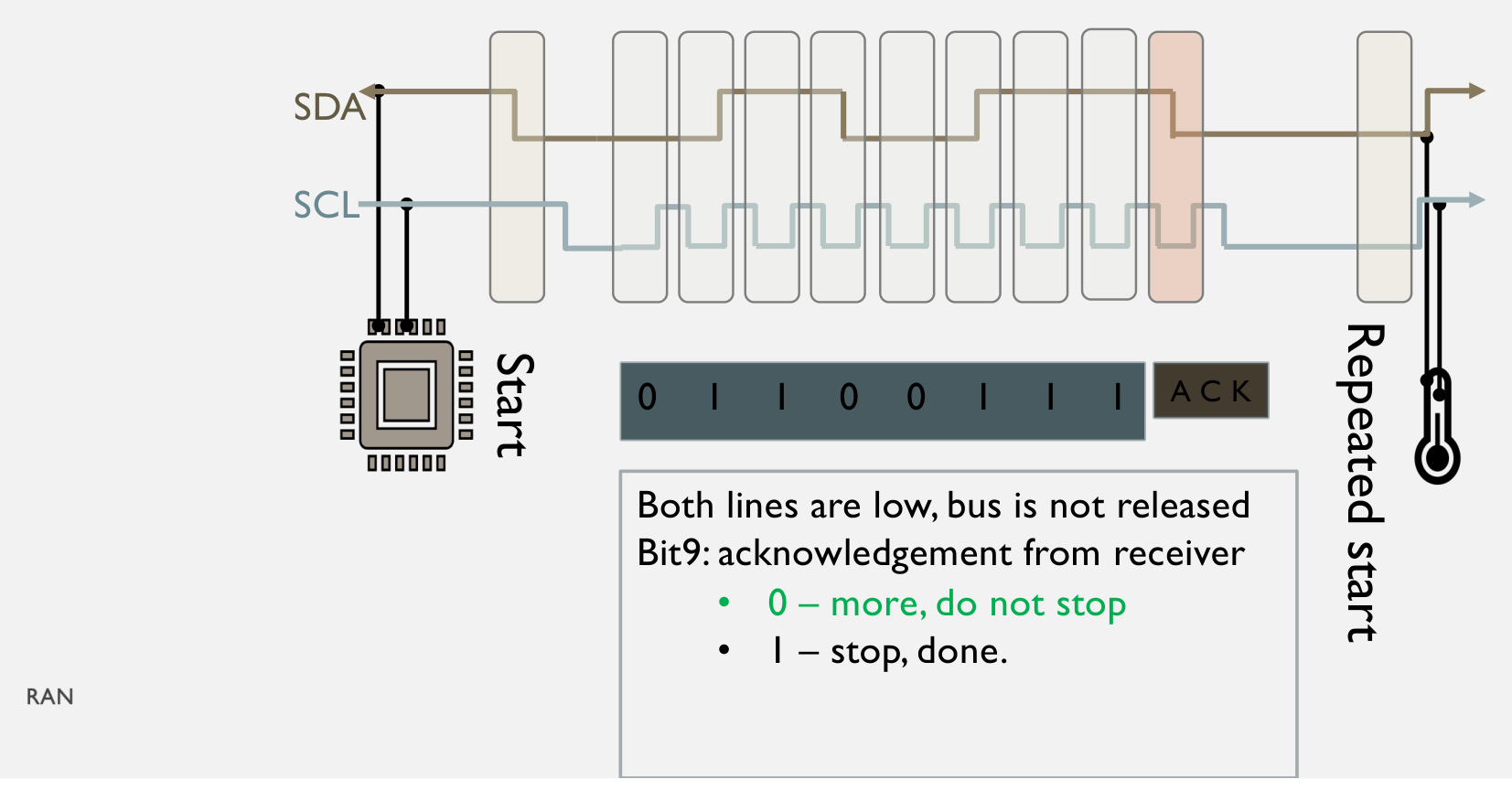
Slide 14 · Nine clocks per byte: the receiver answers I²C byte followed by an acknowledgement: the receiver holds SDA low on the ninth clock, indicating that more data may follow without a stop condition.
Slide 15 · NAK: nobody pulled the line down I²C byte followed by a negative acknowledgement: SDA is high on the ninth clock, signaling completion; a stop condition ends the transaction.
Slide 16 · Address byte: 7 bits plus a direction I²C read transaction: start condition, seven address bits sent most-significant first, read bit equal to one, acknowledgement, and repeated start. SDA carries data and SCL clocks each bit.
Slide 19 · Four blocks, four wires MCP9808 temperature-sensor breakout board with labeled Vdd, ground, SCL, SDA, alert, and address-selection pins A0, A1, and A2. Photo: Adafruit.
Complete notes Lab 6 manual